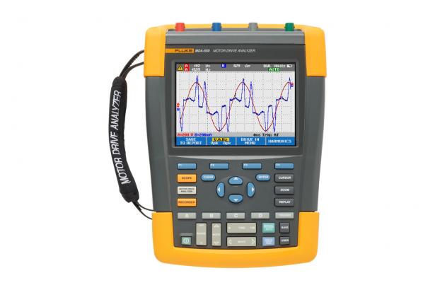
雷竞技appFluke MDA - 510 and MDA - 550 motor driven analyzer
The main features
- Conductive measurement using graphical connection diagram, step by step voltage and current of variable frequency drive Settings and the connection becomes more easily than ever before
- Default configuration of measurement according to the selected test program to collect data, the need for complex configuration
- Built-in report writing can be adjusted easily generate professional troubleshooting report before/after adjusting motor drives
Produc雷竞技appts overview: Fluke MDA - 510 and MDA - 550 motor driven analyzer
Using heuristic test set up and automation drive measurement to provide reliable and repeatable test results, the troubleshooting work change numerous for brief motor drives.
雷竞技appFluke MDA and MDA 550 Motor - 510 Drive Analyzer can not only save time and avoid complex measuring set brings trouble, at the same time also can simplify the troubleshooting process of variable frequency Drive.Only need to select a test, the next step by step heuristic measurements will show where you need to establish a connection, the voltage and current at the same time, the default configuration of measurement to ensure that you collect to each key motor drive - a part of all the necessary data from the input to the output, the dc bus and motor itself.From the basic to advanced measurement, MDA - 500 series to achieve universal coverage, and use the built-in report generator, you can quickly, easily and confidently to generate calibration before and after the calibration reports.
MDA - 510 and MDA - 550 is an ideal portable motor drive analysis tool, can help you to find out and eliminate the working motor drive system of all kinds of common problems.
- Measure the main parameters of motor drives, including voltage, current and dc bus voltage level and ac voltage and current ripple, unbalance and harmonic (MDA - 550), voltage modulation and motor shaft voltage discharge (MDA - 550).
- Perform extended harmonic measurementTo determine the low time and the impact of higher harmonic of power system for you.
- The measurement of conductiveBy using graphical connection diagram, step by step voltage and current of motor drive input, dc bus, the output and input motor and motor shaft (MDA - 550) was measured.
- Using the simplified measurement setupAnd default configuration of measurement, according to the selected test program automatically trigger data collection.
- Quickly and easily create a report, especially suitable for record any troubleshooting log and collaboration with others.
- Additional electrical parameter measurement, with the aid of the complete 500 MHz oscillographic table, instruments and recording function, to conduct a comprehensive industrial system of electrical and electronic measurement.
雷竞技appFluke MDA - 510 and MDA - 550 motor driven analyzer USES heuristic test and measurement, make it easier than ever to analysis.
Drive input
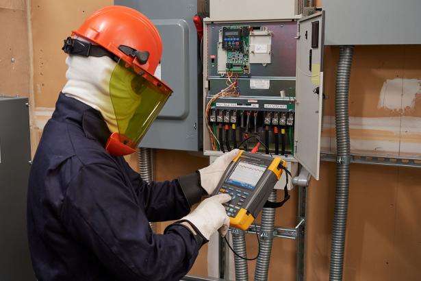
By measuring the input voltage and current, and then by using a variable frequency drives (VFDS) (also called variable speed drive (VSD) or adjustable speed drives (ASD)) of the nominal voltage rating compared with the actual supply voltage to quickly check to see if the value in the range of acceptable limits.And then, check the input current, determine whether current in the range of maximum rated, and cable specifications.You can also through the visual check waveform shape or view the total harmonic distortion and harmonic spectrum of single harmonic screen (MDA - 550), check whether the harmonic distortion is at acceptable level.
Voltage and current unbalance
Inspection frequency control input terminal voltage unbalance of the driver, to ensure that the phase imbalances will not too high (< 2%) and phase sequence is correct.You can also check the current imbalance, because excessive imbalances may said rectifier drive has a problem.
Extended harmonic measurement
Harmonic too much will not only threaten the safety of the rotating machine, the other devices connected to the power system is also a threat.MDA - 550 can find harmonic of motor drives, can also find inverter switch components might affect.MDA - 550 has three harmonic range, 1 to 51 harmonics, 1 to 9 kHz and 9 kHz to 150 kHz super harmonic, able to find any harmonic pollution problem.
The dc bus
In motor drive, drive the internal ac - dc conversion is critical, in order to obtain better performance, the drive must ensure and maintain a low ripple voltage accurately and fully filtering level.High ripple may malfunction or capacitor are connected by the specifications of the motor is not correct.The record function of the MDA - 500 series can be used for the load on the working mode of dynamic inspection on the performance of the dc bus.
Driver output
Mainly by measuring the voltage frequency ratio (V/F) and voltage modulation depth to check output inverter drives.When the measured value of the V/F ratio on the high side, the motor could overheat.When the V/F ratio is low, the connected motor may not be able to provide the needed on the load torque, it can no longer be fully expected process operation.
Voltage modulation
Using pulse width modulation signal measurements to check for possible damages to the motor winding insulation of high voltage peaks.Pulse rise time or gradient through the dV/dt readings (voltage within a certain time rate of change), this reading should be compared with the insulation value of the motor.These measurements can also be used to determine the switching frequency, the electronic switch fluctuations occur to determine signal or ground whether there is a potential problem.
The motor input
Ensure input terminal connected to the voltage for the motor is crucial, and reasonably select the drive and motor wiring between the same key.The wrong wiring figure that produced the drive and motor damage due to the reflection peak voltage is too high.Check terminal on the current in the motor rating scale is very important, because the current is too high will lead to motor overheating, and thus shorten the life of the stator insulation, lead to motor failure in advance.
The motor shaft voltage
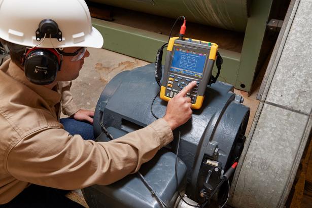
From the variable frequency drive voltage pulse may a coupling between the motor stator to the rotor, which may lead to a voltage to appear on the rotor shaft.When the rotor shaft voltage exceeds the insulation voltage of the bearing grease, may appear flashover current (spark), leading to a motor bearing race corrosion pitting and groove, this damage can lead to premature failure of the motor.MDA - 550 series brush probe analyzer with carbon fiber, can easily detect whether there is a destructive shaft voltage (flashover current), at the same time, pulse amplitude measurement and the counting function allows you to take measures before the failure occurs.Attachment and MDA - 550 function allows you to find the potential damage, without having to invest costly permanent installation type solution.
Heuristic measure to ensure it step by step when you need to provide the required data
MDA - 500 series is designed to help you quickly and easily detection and elimination of the three-phase and single-phase electric motor drives the working system of all kinds of common problems.With information on the screen and step by step wizard, you can easily configure analyzer and obtain the required drive measure, thus rapid maintenance to make better decisions.From the power input port to the installed motor, MDA - 500 provided by the measurement function allows you to quickly troubleshoot for motor drives.
Produc雷竞技appt specifications: Fluke MDA - 510 and MDA - 550 motor driven analyzer
| Measurement functions | |
|---|---|
| Dc dc voltage (V) | |
| The maximum voltage, 10:1 or 100:1 probe | 1000 V |
| The maximum resolution, 10:1 or 100:1 probe | 1 mV |
| Full scale reading | 999 count |
| Accuracy, 4 s to 10 us/div | Counting 3% plus or minus (+ 6) |
| Ac voltage (V) | |
| The maximum voltage, 10:1 or 100:1 probe | 1000 V |
| The maximum resolution, 10:1 or 100:1 probe | 1 mV |
| Full scale reading | 999 count |
| 50 Hz | + + 10 counts (3%) to 0.6% |
| 60 Hz | + + 10 counts (3%) to 0.4% |
| 60 Hz and 20 kHz | + + 15 counts (4%) |
| 20 kHz to 1 MHz | + + 20 count (6%) |
| 1 MHz to 25 MHz | + + 20 count (10%) |
| True RMS voltage (V ac + dc) | |
| The maximum voltage, 10:1 or 100:1 probe | 1000 V |
| The maximum resolution, 10:1 or 100:1 probe | 1 mV |
| Full scale reading | 1100 count |
| Dc to 60 Hz | Plus or minus 3% (+ 10 counts) |
| 60 Hz and 20 kHz | + + 15 counts (4%) |
| 20 kHz to 1 MHz | + + 20 count (6%) |
| 1 MHz to 25 MHz | + + 20 count (10%) |
| Voltage (V PWM pulse width modulation) | |
| use | Pulse width modulation (PWM) signal measurement, such as motor drive inverter output signal |
| The principle of | Reading showed is based on the basic frequency of the number of the whole cycle sampling average to obtain the effective voltage |
| precision | The same as the sine wave signal of Vac + dc |
| Peak peak voltage (V) | |
| model | Maximum, minimum peak or peak to peak |
| The maximum voltage, 10:1 or 100:1 probe | 1000 V |
| The maximum resolution, 10:1 or 100:1 probe | 10 mV |
| precision | |
| Maximum, minimum peak | Plus or minus 0.2, |
| Peak to peak | Plus or minus 0.4, |
| Full scale reading | 800 count |
| The general specification | |
|---|---|
| Current (AMP), the use of current clamp | |
| range | With the V + dc or ac, Vac V peak is the same |
| The scale factor | 0.1 mV/A, 1 mV/A, 10 mV/A, 20 mV/A, 50 mV/A, 100 mV/A, 200 mV/A, 400 mV/A |
| precision | Same as the Vac, Vac + dc or V peak (add current clamp accuracy) |
| Frequency (Hz) | |
| range | 1.000 Hz to 500 MHz |
| Full scale reading | 999 count |
| precision | Counting (plus or minus 0.5% + 2) |
| Voltage/frequency ratio (V/Hz) | |
| use | Displayed in the variable speed ac motor speed drive PWM value of V (see V PWM) divided by the results of the fundamental frequency |
| precision | % Vrms + % Hz |
| Drive input voltage imbalance | |
| use | According to a certain phase voltage divided by the percentage of average income three true RMS voltage difference |
| precision | Based on the Vac + dc indicative percentage of the value |
| Output and input motor voltage imbalance drives | |
| use | Shows a divided by three phase voltage PWM voltage maximum difference in the percentage of average income |
| precision | Based on the percentage of indicative V PWM numerical |
| Input current imbalances drives | |
| use | Display a divided by three phase current ac current value the highest difference between the average income percentage |
| precision | Based on the indicative percentage of the Aac + dc value |
| The input current imbalances drive output and motor | |
| use | Display a divided by three phase current ac current value the highest difference between the average income percentage |
| precision | Based on A percentage of indicative ac values |
| Rise time and fall time | |
| reading | Voltage difference (dV), time (dt), the voltage difference divided by the time difference (dV/dt), overshoot |
| precision | The same as the precision of oscillographic table |
| Harmonic and spectrum | |
| harmonic | Dc to 51 times |
| spectrum | 1...9 kHz, 9-150 kHz) (20 MHz filter, to 500 MHz (voltage modulation) |
| Shaft voltage | |
| Events per second | Based on the rising and falling time (pulse discharge) indicative percentage of the measurement |
| The report data acquisition | |
| Number of screen | Report, can save 50 pages of typical screen (depends on compression ratio) |
| Transmission to the computer | Use 2 GB USB stick or mini USB to雷竞技app USB tieline and FlukeView ™ 2 for ScopeMeter ™ testing tools |
| Probe setup | |
| Voltage probe | 1:1, 10:1, 100:1, 1000:1, raging, 200:1 |
| Current clamp | 0.1 mV/A, 1 mV/A, 10 mV/A, 20 mV/A, 50 mV/A, 100 mV/A, 200 mV/A, 400 mV/A |
| Shaft voltage probe | 1:1, 10:1, 100:1 |
Mode雷竞技appl: Fluke MDA - 510 and MDA - 550 motor driven analyzer
- 1 piece of BP 291 lithium-ion battery pack
- 1 BC190 charger/power adapter
- 3 root VPS 100:1 high voltage probe, with alligator clip
- 1 root VPS410 - II - R 10:1 500 MHZ voltage probe
- Three i400s alternating current clamp
- 1 only C1740 portable package
- 1 to 2 GB usb flas雷竞技apph drive, including manual and FlukeView ™ 2 software
- 1 set of spatially-integrated SVS - 500 shaft voltage suite (3 brush, probe, two-piece extension rod and magnetic)
- 1 piece of BP 291 lithium-ion battery pack
- 1 BC190 charger/power adapter
- 3 root VPS 100:1 high voltage probe, with alligator clip
- 1 root VPS410 - II - R 10:1 500 MHZ voltage probe
- 1 i400s alternating current clamp
- 1 only C1740 portable package
- 1 to 2 GB usb flas雷竞技apph drive, including manual and FlukeView™2 software
Manual + 雷竞技appresources: Fluke MDA - 510 and MDA - 550 motor driven analyzer
- Five test points in order to understand the efficiency of the motor drive, and performance
- Elevator electronic technical personnel's job is very busy, they through the use of fluke new motor driver analyzer to save time
- Use雷竞技app Fluke MDA - 550 Motor Drive Analyzer to measure the Motor shaft voltage discharge


